
Intro
Without diving into the “why” part, I wanted to make yet another keyboard with Cherry MX keyswitches (just like everyone else these days), and I ended up deciding to make my own keyboard controller (again like everyone else). After all…

(customary https://xkcd.com/927/ )
Apparently, scanning a keyboard matrix is a solved problem. There are two main challenges:
- Detect arbitrary simultaneous key presses. This is usually referred to as NKRO or N-Key Roll-Over (excluding protocol limits, e.g. old USB keyboard drivers). The article already covered the solution: simply add a series diode to each switch.
- Filter out mechanical and electrical transients during a single key-down or key-up event. This is usually referred to as debouncing. There are many sources online that cover this, and equally many solutions — firmware, hardware, and more commonly a combination of the two. See this Wikipedia entry on Switches, and this must-read tutorial by Ganssle.
While guys at Cherry (the company that makes the MX switches) believes otherwise, most other keyboards using MX switches achieve NKRO using the “outdated digital technology” just fine. So I confidently drew my 1st prototype PCB as a 10×10 Cherry MX switch matrix with per-key series diodes, sent it to fab, and started writing my own controller.
Sidenote: Yes, there are MCUs with tons of I/O pins (such as
STM32F100ZCT6) enough to hook up all switches directly, routing the PCB could be a PITA if not impossible under reasonable space constraints (haven’t tried — might end up resorting to autorouter), the MCU takes huge space by itself, and on top of it I can’t really think of any real benefit to this approach.
Scanning
The Task
A keyboard controller reads a key matrix (assuming it has per-switch series diodes) in the same way it reads a multiplexed bus:
Timing diagram created with WaveDrom. See this gist for source and SVG.

- drive only 1st row line to high (the rest hi-z or low)
- wait then read all column lines
- drive only 2nd row line to high
- wait then read all column lines
- …
- drive only last (10th) row line to high
- wait then read all column lines
- (rinse and repeat)
Ignoring the “TIM1” for now (will cover later), the diagram illustrates the sequencing of the row lines (output), the response of the column lines (input), and a possible “strobe” signal, which indicates the exact moments when column lines should be sampled.
On an AVR, this might be done in a idle-spin loop or through interval timer interrupts. If you don’t have enough pins you can always use 2 74HC164‘s (8-bit serial-in parallel-out shift registers), but you still need to manually clock them, either through bit-banging or by feeding bytes to a SPI master peripheral. Sounds like a trivial task burning lots of CPU cycles!
Automate with STM32
I am a big fan of the STM32 series, mostly owing to its well-designed timer peripheral blocks, which are not only very flexible, but also available in even the cheapest variant (e.g. STM32F030C6T6 which retails for USD \$1.69 each on Digi-Key). Common applications include generating complex PWM output signals or reading incremental/quadrature encoders. While the PWM function cannot directly produce our desired row pins driving pattern, it is only a side-effect of the timer’s underlying “output compare” mechanism: An internal event is fired when the timer counter reaches the value stored in a register. This event can be programmed to trigger a variety of behaviors including:
- an output change, which produces a PWM signal on a single pin
- an interrupt request, which we try to avoid so that the CPU is not tied up doing boring I/O
- a DMA request
The DMA request option is interesting. AllSTM32s feature a simple DMA controller with multiple independent “channels” or “streams”; each channel transfers one word (1/2/4 Bytes) of data between a pair of pre-programmed source/destination addresses upon request from a peripheral (it does more but this is what we care about for now). The addresses can be anywhere in the flat 32-bit Cortex-M address space (again greatly simplified; actually depending on bus architecture and address space mapping). Expressed in C it does roughly one of the following (without burning CPU cycles; only consuming memory bandwidth):
for (i = 0 ; i < n ; ++i) while (1) if (requested) { p[i] = *q; break; }
for (i = 0 ; ; i = (i+1)%n) while (1) if (requested) { p[i] = *q; break; }
/* both p and q can be independently configured to be indexed or not */
We need to access many I/O pins at once. By accessing GPIO port registers, the following can be done:
- atomically changing several output pins in a GPIO port without affecting others (in
STM32F0/1/3: write toBSRR(bit set/reset register)) - sampling the value of all (16) pins in a GPIO port (in
STM32F0/1/3: read fromIDR(input data register))
In many cases, one or more timers can actually have multiple DMA request lines connected to different channels. e.g. for STM32F10x, TIM1 has both its update event (happens when the up-counter overflows and resets to 0) and its output compare channel 4 event connected. This allows us to configure said timer alongside with 2 DMA channels and 2 GPIO ports to completely automate the desired I/O sequence:
- Allocate all row output pins on one GPIO port (e.g.
PA3, PA5, PA7, ..., and all column input pins on another GPIO port (e.g.PB4, PB5, PB10, ...(note that pin numbers do not have to be consecutive). - Configure the timer as a PWM timer; the PWM output pin does not need to be connected
- Enable DMA requests for update and output compare events
- The update event is responsible for sequencing the row outputs; configure its corresponding DMA channel to transfer a 32-bit word from an array (see below) to the row GPIO port
- The output compare event after an update event is responsible for reading the column inputs; configure its corresponding DMA channel to transfer a 32-bit word from the column GPIO port to another array (see below)
- Generate an update event (which resets the counter and triggers initial row output DMA request)
- Start the timer
Without considering deadband generation (which by the way can be done although with more effort and memory waste), the two arrays mentioned above can be set up in the following way:
scan_out_raw[N_ROW]stores the register value to be written to the row GPIO port at each “step” in order to output low on all row pins but the indexed row, and output high on this row. This is set as a circular buffer input of the row output DMA channel.scan_in_raw[2][N_ROW]is a double buffer; each half then stores value of all pins in the column GPIO port sampled when each row is active.
How it works
With all the pieces in place, let’s see how they fit together. Here is the timing diagram again:
The TIM1 line shows its counter value. For illustration purposes, suppose the period is 5 (really long) ticks, and the output compare register is set to 4. The following happen during one full period:
- Update event occurs and timer counter becomes 0. This triggers DMA transfer from
scan_out_raw[i]toBSRRof row GPIO port, which outputs the correct row output pattern for this period. - After some delay (DMA, GPIO, signal propagation, capacitance, …), the column lines now read which keys in current row is pressed.
- When counter reaches 4 (== output compare register), column input DMA is triggered, and dumps the column GPIO port pin values from
IDRtoscan_in_raw[j][i](as shown instrobeline).
Notice that the out/in arrays are transferred from/to in lock-step (modulo double buffering). The timer and DMA automatically populates scan_in_raw with the latest scan of the key matrix. While it contains all pins in the column GPIO port, it is trivial to pluck out only the column input pins using some bitwise ops. Other than this, we spend zero CPU cycles during the actual scanning. The hardware worked together to do all the heavy lifting as if we’re using an ASIC. This allows us to use a high scanning rate (e.g. 20us per row, 200us per full scan) while leaving the CPU free to handle other tasks. Amazing.
Debouncing
The Task
The scanning module above effectively samples each key as a discrete-time binary signal. However, this signal does not always reflect the pressed/released binary state of the key switch itself:
- EMI (electromagnetic interference) might cause spikes which could be picked up when the switch is being sampled; this may happen all the time.
- When the switch is being pressed or released and the contacts within the switch is at the boundary of making/breaking, a short burst of oscillating transients almost always occurs as the mechanical system formed by the contacts oscillates. They eventually settle down and come into stable and unambiguous contact or separation as mechanical damping kills the oscillation. This is the “contact bounce” phenomenon. For Cherry MX switches, the transients can last 5 milliseconds after initial edge according to official datasheets.
Here are some typical oscilloscope traces of contact bouncing:

from http://hackaday.com/2015/12/10/embed-with-elliot-debounce-your-noisy-buttons-part-ii

from https://geekhack.org/index.php?topic=42385.0
If a keyboard controller does not take into account of these issues, it would generate spurious key press/release events without corresponding actual key presses/releases. Clearly this is undesirable. “Debouncing”, as the name suggests, refers to producing a signal that is free of above issues and faithfully represent the true state of whether a key switch is pressed or not.
This may sound a lot of hand-waving, so instead let’s start from first principles:
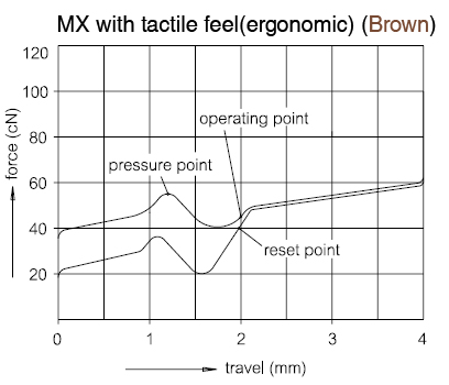
The moving part of a switch is referred to as its “actuator”, and in the case of Cherry MX more commonly as “plunger” or “stem”. We define the vertical position x of the plunger to be 0 when it is released and supported entirely by the spring; x grows positive as the plunger is pressed further down. This position alone provides a ground truth of whether the switch is pressed or not (binary signal): a schmitt trigger on x. Notice that the ground truth has nothing to do with the electrical parts of the switch, and therefore is subject to neither EMI nor contact bouncing. The task of debouncing can then be defined as online (causal) reconstruction or estimation of the ground truth using only the sampled (noisy) electronic signal. Objective of a good debouncer is to minimize both spurious events and delay in its output compared to ground truth, while trying to be modest on computational resources.
Popular Strategies
Analog Filtering
Strictly speaking this is not really a part of the “debouncer” proper, but rather a simple EMI countermeasure. A 1st order low pass RC filter on each column line effectively attenuates the electrical noise.

RC filtered bouncing analog waveform captured from one of my own Cherry MX clear switches
There is a catch, though: while the time constant of this filter is straightforward to choose if only one switch is connected, the key matrix case is much more complex due to scanning. The time constant must be much smaller (say, 1/4) than the total duration a particular row is active (i.e. the period of TIM1 in the scanning timing diagram), so that the transients caused by scanning can die off.
Another detail applies to SPST switches with pull-up/-down resistors: You need a bypass diode to ensure symmetrical time constants when the switch makes vs. breaks. See Ganssle’s article for details.

Consecutive Runs
Many debouncers make decisions by counting consecutive 1’s or 0’s in the sampled input. Here is a sophisticated example which is an improved version of someone else’s counting code.. The core idea is we can be reasonably sure that a switch is not bouncing — that is, in steady state instead of transient — when the reading from it remains the same for long enough.
Main disadvantage of this approach: since it effectively waits for the contact bounce to completely die out before it can make a decision, the delay can be too long. While this is generally okay for typing, it is unacceptable in real-time applications such as gaming.
Integrator/Accumulator/Counter
Formulae might not be formatted due to bad support of wordpress.com on MathJax
Another way is to consider the scan input as {-1, +1} as opposed to {0, 1}, then use a saturated integration/accumulation of this signal across time. In the continuous-time form:
$$
y = \int_0^T \mathbf{1}_{\,0 < y < 1}\cdot\frac{x(t)}{\tau}\,dt
$$
where $\tau$ is a time constant that determines how fast $y$ can swing from one end (e.g. 0) to the other (e.g. 1). Higher values lead to more delay but also more robustness. When $y$ reaches $0$, output of the debouncer is set to low; similarly $1$ sets output to high.
The continuous time equation can be converted to discrete time integer accumulation by scaling $y$ by $\tau/\Delta t$, so that at every time-step $y$ can be simply incremented or decremented by 1 then compared to a larger integer boundary.
While this approach could be less robust than the consecutive run approach, its delay is no longer than the consecutive run approach even when the same time constant is used. This is because the counter may still make progress during contact bounce.
The "Quick Draw"
(I made up the name).
This approach puts minimal delay far in front of robustness. Due to causality (i.e. you cannot predict the future), the earliest moment a debouncer can claim a transition is the first time its input changes. This is exactly what The Quick Draw approach does, with a single twist: After this transition, since we know that more bouncing is coming, the algorithm waits for a certain duration before it reads this key again, so that it does not misfire on the subsequent bouncing transients, and hopefully arrive directly at steady state.
Main disadvantage is of course robustness. It is extremely susceptible to EMI that escapes the hardware filter, as well as temporary breaking caused by aged metal contacts (which behaves in similar ways as EMI but is somehow coupled to the mechanism).
It is worth noting that some custom keyboard controllers (forgot source) selectively apply this method on demand, e.g. during gaming sessions. Also, it might work surprisingly well enough when the plunger goes from released to pressed (making contact), because we are certain that the bouncing cannot occur if the button is not pressed in this case.
A Hybrid Approach
So we're starting to see a trade-off here: delay vs. robustness. As an attempt to make this tunable and achieve a compromise between the two, I conceived a slightly more complex counter and state-machine based algorithm.
Before diving into the algorithm, though, notice that all above algorithms are symmetric, meaning that they do not distinguish between making and breaking of contacts. A reason against asymmetric algorithm is that doing so would require physical modeling of contact dynamics, which can be prohibitively hard. Even if we could come up with a model for one particular switch, an algorithm that takes advantages of it would likely not work as well on other switches. Therefore, the practical choice is to accept any asymmetry present in the physical system as unmodeled dynamics and create an algorithm that works anyway.
The general idea is to have 2 classes of states: steady-state and transient. We keep a counter for each key that increments/decrements when input is high/low respectively, similar to the purely counter-based approach mentioned above, with a notational difference for convenience: the counter is clipped between -s to +s.
The (symmetric) state machine is as follows:

- A key starts in steady-state low, with counter saturated at
-s. In this state we are confident that the key is not pressed until we start to see a few1's at input, which likely indicates a low-to-high transient. This "transient detection" is done by comparing the counter against a threshold-s + t, wheretis the number of consecutive1's it takes for the algorithm to confirm a transient. - Once the transient is confirmed, we immediately switch the output to high. At this time the contacts are likely to be still bouncing, and we wish to ignore that until they settle down. This is the opposite problem from last: we are trying to detect steady-state. Note that the key might end up in either low or high when it settles down — the algorithm was convinced that the key is pressed, but however unlikely it might appear, this could have been a false alarm. A way to find out is to reset the counter to
0(neutral between low and high), and wait until it reaches either-sor+s. If it reaches+sthen we know for sure that the key has ended up being pressed (and is now steady-state high);-swould mean the algorithm made a mistake and we need to switch the output back to low.
The high-to-low cases are identical except for flipped signs.
While I have yet to sample any real bouncing on my brand-new Cherry MX clear (they are surprisingly clean — 2 to 4 bounces that last less than 100us in total), I would imagine such an algorithm robust enough to match just about any switches out there if s and t thresholds are picked according to the characteristics of the particular switch. It is flexible: you can trade delay for robustness by increasing the thresholds and vice versa.
I packed this algorithm into a class and tested it on my complete keyboard system and it worked perfectly so far with negligible delay (t was set to confirm transient in 600us, or 3 scan cycles, if no bouncing; more if bouncing gets sampled). Code as follows:
This file contains bidirectional Unicode text that may be interpreted or compiled differently than what appears below. To review, open the file in an editor that reveals hidden Unicode characters.
Learn more about bidirectional Unicode characters
| #pragma once | |
| #include <cstdint> | |
| #ifdef DEBOUNCER_CHECK_TYPE | |
| # include <type_traits> | |
| #endif // DEBOUNCER_CHECK_TYPE | |
| template <typename T, T thres_transient, T thres_steady> | |
| struct Debouncer { | |
| #ifdef DEBOUNCER_CHECK_TYPE | |
| static_assert(std::is_signed<T>::value, ""); | |
| #endif // DEBOUNCER_CHECK_TYPE | |
| static_assert(thres_transient > 0, ""); | |
| static_assert(thres_steady > thres_transient, ""); | |
| static const T thres_transient_abs = thres_steady – thres_transient; | |
| static const bool LO = false, HI = true; | |
| // discrete integrator | |
| T counter; | |
| // finite state machine | |
| // | # | state | out | | |
| // |—|——————–|—–| | |
| // | 0 | seady-state lo | lo | | |
| // | 1 | transient lo-hi | hi | | |
| // | 2 | steady-state hi | hi | | |
| // | 3 | transient hi-lo | lo | | |
| std::uint8_t state; | |
| // always initialize from steady state | |
| void init(bool value) { | |
| if (value) { | |
| counter = +thres_steady; | |
| state = 2; | |
| } else { | |
| counter = -thres_steady; | |
| state = 0; | |
| } | |
| } | |
| Debouncer(bool value = LO) { init(value); } | |
| // shorthands | |
| operator bool () { return output(); } | |
| bool operator() (bool input) { return update(input); } | |
| // output is determined by state | |
| bool output() { return state == 1 || state == 2; } | |
| // run debouncing algorithm for one timestep | |
| // return: whether output has changed | |
| bool update(bool input) { | |
| if (input) { | |
| if (counter < +thres_steady) ++counter; | |
| } else { | |
| if (counter > -thres_steady) –counter; | |
| } | |
| switch (state) { | |
| case 0: // steady-state lo | |
| if (counter >= -thres_transient_abs) { | |
| // => transient lo-hi | |
| counter = 0; | |
| state = 1; | |
| return true; | |
| } else { | |
| return false; | |
| } | |
| case 1: // transient lo-hi | |
| switch (counter) { | |
| case +thres_steady: | |
| // => steady-state hi | |
| state = 2; | |
| return false; | |
| case -thres_steady: | |
| // => steady-state lo | |
| state = 0; | |
| return true; | |
| default: | |
| return false; | |
| } | |
| case 2: // steady-state hi | |
| if (counter <= +thres_transient_abs) { | |
| // => transient hi-lo | |
| counter = 0; | |
| state = 3; | |
| return true; | |
| } else { | |
| return false; | |
| } | |
| case 3: // transient hi-lo | |
| switch (counter) { | |
| case +thres_steady: | |
| // => steady-state hi | |
| state = 2; | |
| return true; | |
| case -thres_steady: | |
| // => steady-state lo | |
| state = 0; | |
| return false; | |
| default: | |
| return false; | |
| } | |
| default: | |
| // should panic, but `throw` isn't always available… | |
| return false; | |
| } | |
| } | |
| }; |
Crazy Idea: LSTM?
After formulating the debouncing problem like above, I realized that it is in essence a simplified variant of my 10-701 Machine Learning final project. That project aims to detect from motion capture data of human walking (on a treadmill) whether each foot is bearing weight or not (stance or swing) at any given time. We approached the problem using — you don't even need to guess — deep recurrent neural network, specifically LSTM. It doesn't matter what the inputs are — it matters that the network basically (causally) recovers a low-frequency binary time-series from a number of other real-valued time-series. If you replace the input with what we get from the matrix scanning, the network becomes a debouncer!
While I have not proceeded with this idea, since both input and output are exactly 1D, I would estimate that a small network will probably do just fine (say, 5 LSTM cells), and evaluation should not take too much computational power — might even be possible on an MCU if optimized properly. Fixed point math and crazy approximations should be used to speed things up further.
Main disadvantage: Supervised learning. Large amount of labeled data is required. This data can be automatically generated though: a viable approach is to use a hobby servo to repeatedly press the key and record both the servo position and the switch response. The position can be used to derive a ground truth signal.
Future: Cherry MX Mods?
I know these switches have been basically the same as when they were first invented in 1980. Honestly I like the force profile of the tactile and click switches (not so much of linear switches because nothing is special about Hooke's Law). With my mechanical/automation background I very well know the importance of these human-machine interfaces — even in factories with large levers, buttons, footswitches, overtravel bumpers, etc. However, instead of mechanical contacts, switches intended to control small signals have a better option than mechanical contacts: optical, Hall effect, both of which already intensively used in industrial automation and even used in some keyboards: this one made by Bloody and some obsolete stuff made by Honeywell which somehow became part of the history thanks to the Lisp Machine's Space Cadet Keyboard.
So instead of "patented golden cross-point technology", how about replacing only the metal contacts with a hall effect sensor? This way we can directly and reliably measure the plunger position and totally avoid the bouncing problem. Better still, we can also get the velocity of key presses, which is useful in musical applications. All this can be done without changing the "feel" of the switch itself…
Sounds perfect, although this is way out of my scope. Modifying a single Cherry MX might be marginally doable for me due to precision work on injection-molded plastics; scaling this to a whole keyboard would be outright impossible at the moment.

Hello!
Really, really nice article (or log or whatever)
I do not have any background related to electric stuff, but I wanted to make a keyboard. Your article helped me a lot in clarifying stuff like matrix scanning. First, I wanted to let you know that the diagrams are gone. Can you update it so I can have a look at it? Also, I wonder if the press of the switch will be counted when the matrix scan algorithm checks for the signal the exact moment in which the bouncing causes the signal to be seen as not pressed (sorry, dont know the right terms.) And if you have finished building the keyboard, can you show me some pictures of it? I am not sure about how I have to wire it up, since I do not know about PCB designing/manufacturing while you said the Quick Draw method will be susceptible to EMI.
Thank you!
LikeLike
Forgot about adding this part!
According to a reddit post, the Cherry Realkey was designed to be a cheaper solution since it does not require diodes for NKRO. Does that also mean easier to implement when it comes to detecting the keypresses and debouncing them?
LikeLike
I do not have a copy of Cherry RK, but judging from the PCB screenshots I can get off the Internet it seems that they have added lots of thru-hole resistors in their design. I think they went with that design mostly to reduce scanning cycle period (not save cost), but the effect is dubious.
Personally I would go with the various optical or magnetic based switches instead. They fundamentally solve the problem of mechanical contact bounce.
LikeLike
Thanks for pointing out the broken link. Seems that my image host had gone under.
I think what you mean by “the exact moment” is that you worry whether the scanning, which is a form of sampling at equal time intervals, will be “fooled” by bouncing at exactly that interval. This is called aliasing, and is prevented by the resistor and capacitor, which together form a low-pass filter that “slows down” the bouncing waveform enough for the sampling not to be “fooled”. You can read more about this in a digital signal processing textbook.
PCB routing does not need any special attention. These are just switches after all. The transient (i.e. the moment you press the key) might be noisy, but there is no real high-frequency signal.
LikeLike
Pingback: Slow Software – 4latestnews.com
Pingback: [Перевод] Медленный софт — iT ОБОЗРЕВАТЕЛЬ
Pingback: Key debouncing and scanning – sophisticated – Hallo, here is Pane!